- Summertime is Summer Tire Check Time: 7 Tips To Combat 11,000+ Tire-Related Accidents Annually — and Keep Tires Rolling for Longer
- 10 DIY Tips to Add Years to a Vehicle’s Life & Minimize Expensive Repairs
- Defensive Driving Tips to Avoid Costly Repairs As Wintery Driving Conditions Continue to Plague Roads
- AutoPartsWarehouse.com 2013 Child Passenger Safety Tips and Resource Guide
- Top Five Parts to Make Your Vehicle More Fuel Efficient
Review: APA/URO Radio Antenna
Product: APA/URO Radio Antenna
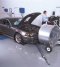
Vehicle: 1981 Porsche 911SC
Level of Difficulty: Easy
Owner: George Weigand
Overview
Porsche parts can be expensive and most people think you have to visit the dealer for replacement parts. It turns out that AutoPartsWarehouse.com offers a great alternative for just over $50.00. The following photos and notes describe replacing an existing automatic power antenna on a 1981 Porsche 911 with a new antenna provided by URO Parts.
Note: This process can easily be performed by one person in 1-2 hours with no special tools. However, it is even easier and faster when two people do the job, as 4 hands are better than 2 when installing the upper mounting pieces and aligning the antenna assembly in a vertical position.
Tools Required
Here are basically the only tools needed:

Tools needed for Radio Antenna Installation
Installation
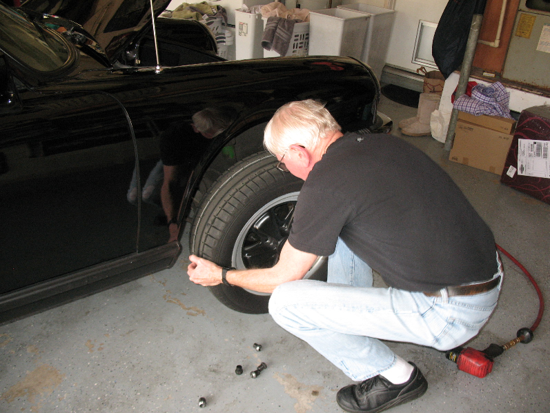
- Jack up the car and remove the right front wheel.
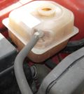
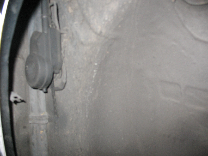
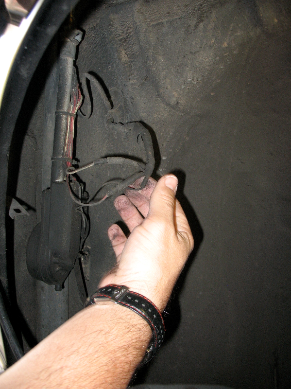
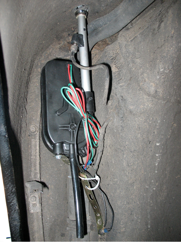
- At this point, it is recommended to take a photo of the existing antenna motor assembly as it is mounted on the inner fender wall; and use this photo for future reference if necessary (here is a photo of my old antenna).
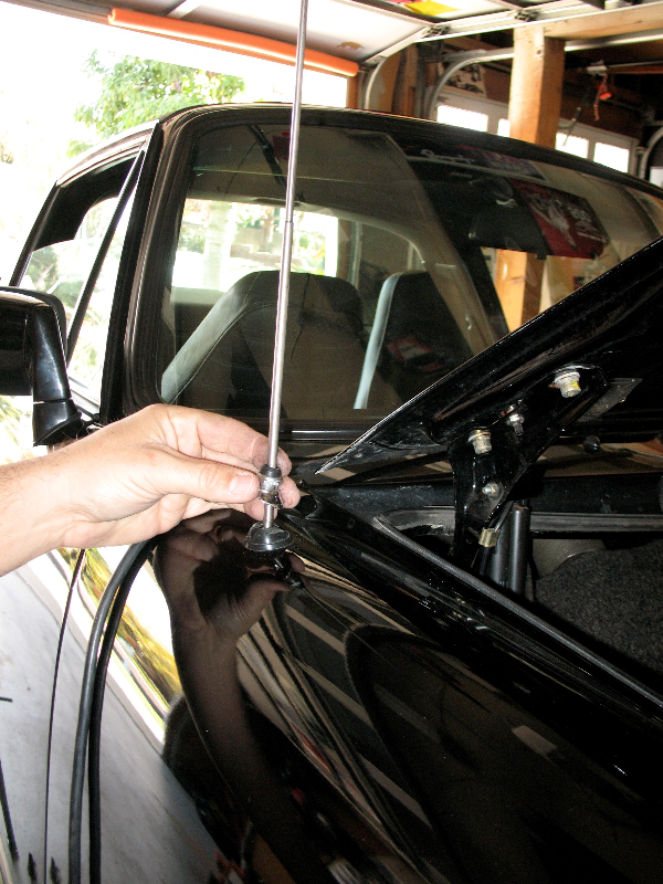
- Loosen mounting nut at tip of antenna (that part that extends through the top of the fender) and carefully remove the nut, dome cap, insulator, and rubber gasket. TIP: keep these parts and store them in the exact order and orientation as they were mounted; as you may want to reinstall these parts on the new antenna. Even if you use the new parts that came with the new antenna, you may need to refer to how the old parts were oriented, when installing the new parts.
- After removing the screw that connects the support strap to the fender wall, rotate the motor housing so as to allow easy access to the wires.
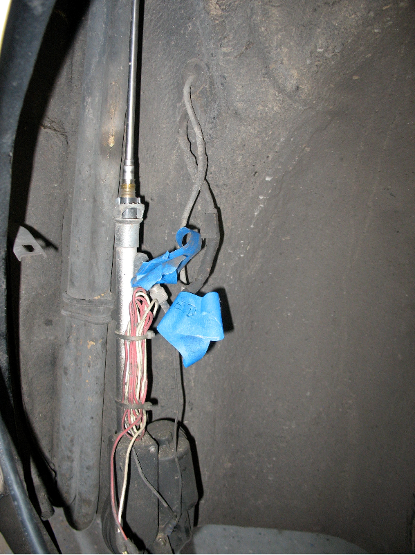
- If necessary, tag the wires that go to the radio. There should be three wires; 1-red, 1-white or green, and 1-black. The black wire should be attached to the screw that attaches the support bracket to the antenna motor housing, or it may be attached to the screw that attaches the support bracket to the inner fender wall. There should also be a black wire from the motor housing attached to this same screw. NOTE: For the antenna motor to function properly, both of these two black wires have to be connected together at the point where the support bracket is screwed onto the antenna motor housing, or at the screw used to attache the support bracket to the inside fender wall, thus providing a good “electrical ground”. The antenna motor will not work properly without a good “electrical ground”.
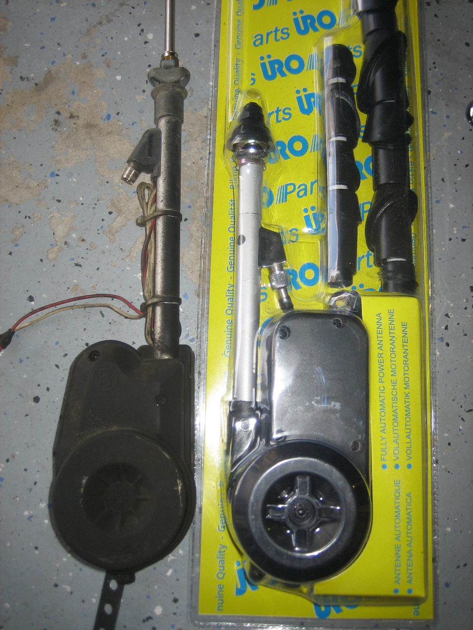
- Cut the black wire leading from the antenna motor housing and disconnect the three wires that go to the radio (the existing connections may be in-line male/female plugs and sockets); and unscrew the existing antenna cable from the existing antenna mast. The old antenna assembly can now be removed from the car. NOTE: At this point it is recommended that you place the old antenna alongside the new antenna assembly for a comparison.
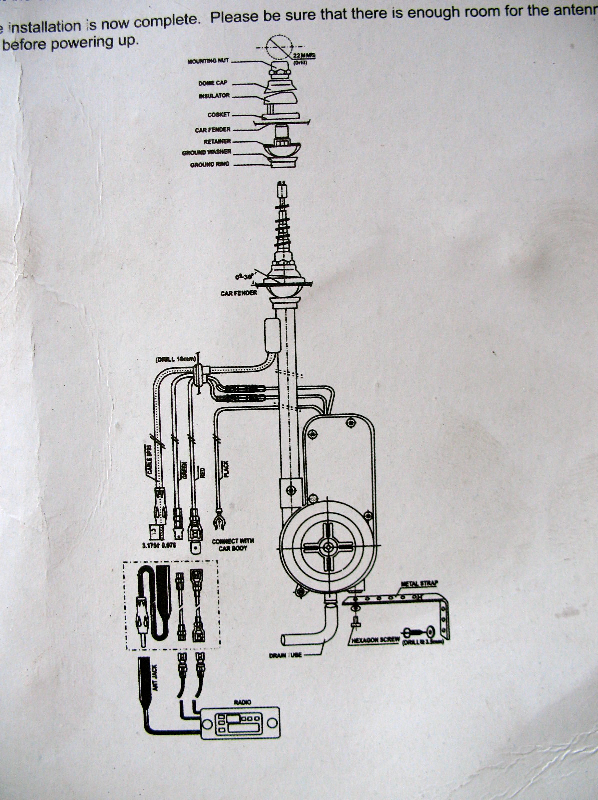
- This is a good time to review the installation instructions that came with the new antenna; especially the diagram shown here. Pay particular attention to each and all of the pieces that will mount just below and above the fender, as they have to be installed just right in order for the antenna to end up in a vertical position with a tight weather proof connection. TIP: You may need to use some of the old parts in order to get a good fit.
- Install necessary connectors on all wires. The existing wires from the radio may already have some sort of in-line connector. If so, you should be able to find matching connectors from local electronic stores or even home improvement stores. Or, you can just cut off any existing connectors and then install new connectors of your choice.For the black wires, it is best to install spade lugs, as these wires will be connected to a screw terminal either on the new antenna motor housing or on the screw used to attach the support bracket to the inner fender wall.
- Mounting parts selection.Remove new antenna from packaging and lay all the parts on the floor. The kit contains several different size and shape “Base” components (see diagram and instructions provided with the antenna). Compare the parts on the old antenna with the new parts. Depending on the condition of the old parts, you may want to reuse them if possible. If not, choose the new parts that closely match the old parts, as this will make installation go more smoothly. Note: The new dome cap is plain black where as the old dome cap may be chrome, and may look better when installed than the black dome cap.
- Installing the new antenna. Note: This is where 4 hands are better than 2 hands, so hopefully you have a friend to help.Assemble the ground ring, ground washer, and retainer onto the antenna shaft in the order as shown on the diagram in step 7.Insert antenna shaft up through the hole in the fender. Make sure that the retainer rests evenly on the underside of the fender to prevent any possible damage to the vehicle. Assemble the rubber gasket, insulator, dome cap and mounting nut to the top of the antenna. At this point, only tighten the nut part way.
- Attach support bracket and connect wires and drain tube. See photo below. Attach support bracket to antenna motor housing and to inner fender wall. Do not tighten screws till later.Connect wires and screw on the antenna cable to the antenna motor housing.Note in the photo that the black wire from the motor housing and the black wire from the radio are both attached at the screw holding the support bracket to the inner fender wall. It is important that this connection make good contact with the metal of the fender wall, as this forms the “ground” point, and the antenna motor will not function if this is not a good connection. Attach plastic drain tube.
- Operational Test Turn on radio and test to see if the antenna properly extends and retracts. If so, then continue on to step 13. If the antenna fails to operate, then most likely one or more wires are not making good contact, so double check all connections especially the ground connections provided by the black wires from the motor housing and the radio where they are connected at the support bracket and the fender wall.
- Final alignment and tightening of cap nut. While holding the motor housing, align the mast vertically, ensuring that the “retainer” is resting evenly on the underside of the fender. Arrange the insulator and dome cap so as there is no opening left for water to get into. Firmly tighten the cap nut. Do not tighten this nut excessively as this may strip or break the mounting threads. Tighten the screws holding the support bracket to the motor housing and the inner fender wall.
- Replace front wheel, lower the car, and enjoy your new automatic power radio antenna.
Step 1
Related Posts


-
 Kendall Motor Oil Knowledge Session-Things to know about Full Synthetic Motor Oil Additives
By AutoPartsWarehouse Staff, images courtesy of Kendall Motor Oil...
- November 10, 2017
-
 Kendall Motor Oil Knowledge Session-Things to know about Full Synthetic Motor Oil
By AutoPartsWarehouse Staff, images courtesy of Kendall Motor Oil...
- November 10, 2017
-
 Autolite Iridium XP Spark Plug Install
by Steve and Gavin Maloof The guys at AutoPartsWarehouse...
- August 2, 2017
-
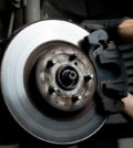 Car Care 101: Common Reasons Why Your Brakes Squeak
Does it bother you when you hear unusual noises...
- June 28, 2017
-
 Car Care Checklist for Summer: Part II
Here are more things to consider to get your...
- June 24, 2017
-
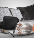 Top Five Auto Parts the Average Consumer Should Purchase Online — and Here’s Why!
AutoPartsWarehouse.com says the Internet is the best place for...
- January 21, 2013
-
 Summertime is Summer Tire Check Time: 7 Tips To Combat 11,000+ Tire-Related Accidents Annually — and Keep Tires Rolling for Longer
U.S. drivers put almost 3 billion miles on their...
- June 4, 2014
-
 AutoPartsWarehouse.com 2013 Child Passenger Safety Tips and Resource Guide
A Wake Up Call On Child Passenger Safety The...
- September 12, 2013
-
 6 Amazing Classic Car Restorations
Restoring old cars always come with a hefty price...
- November 24, 2014
-